Restoring the Beogram 7000 - Changing the electronic components

Restoring the Beogram 7000 - Changing the electronic components

Produced from 1992 to 1996, the Beogram 7000 was the last in the line of high-end turntables from Bang & Olufsen before the CD took over. It is automatic and remotely controllable via the Beolink 7000 or Beolink 5000 and is considered the Holy Grail of modern turntables with a built-in RIAA preamplifier and tonearm with OPP. It is a wonderful piece of engineering and nice and easy to operate. Furthermore, it looks perfect as a part of the BeoSystem 7000 resting on the F1000 desk.

This article explains how to perform a complete restoration of a Beogram 7000 type 5981, but please take note that it is a work in progress and all sections might not be completed yet. It applies to all Beogram turntables of type 59xx. Please refer to the manual whenever a part number is mentioned.

The article is divided into multiple sections, which cover the following subjects:

  1. Opening the Beogram
  2. Replacing the components
  3. Adjustments and other common issues

Opening the Beogram

Opening the Beogram is straightforward. First, you must remove the platter and the pickup and then slide the tonearm as far left as possible. Afterwards, remove the two small screws found at the bottom on the right side of the turntable. 
1

Lift the right side of the turntable and use the support service (1064) to lock it open as seen below.
2

I always remove the rear plate and dust cover since I find the turntable easier to work with and easier to clean. There’s usually dust in all inaccessible places, as seen below.
3

The rear plate (1038) is removed by lifting it upwards after removing the two screws (2) on the back.

The dust cover is removed by disassembling the lid damper (1006) and spring (1007) and then removing the screw attached to the hinge (1008).
4

5

Replacing the components

Because of their construction, aluminium electrolytic capacitors have a finite life. They become dry, weaken, become resistant, increase ripple, to name a few. All issues you don't want in your electronic circuit. Therefore, all the electrolytic capacitors must be replaced. 

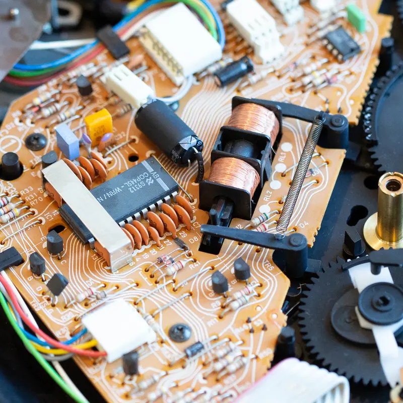
On the control circuit (PCB1, 8005143) 

There are only two capacitors on the control circuit that need to be replaced. It's the 470uF/16V (C2) and the 2.2uF/50V (C28). 

To remove the control circuit you need to remove the four screws marked as (7) below. 

6

The spring and piston also need to be removed. After the spring is removed, you can remove the piston (1646), but take note of the direction. It needs to be inserted in the same direction when assembling it. 
7

After the screws, spring, and piston are removed, you can remove all the cables and slowly wiggle the control circuit free.
The capacitors were replaced by standard 470uF/50V and 2.2uF/50V capacitors.
8

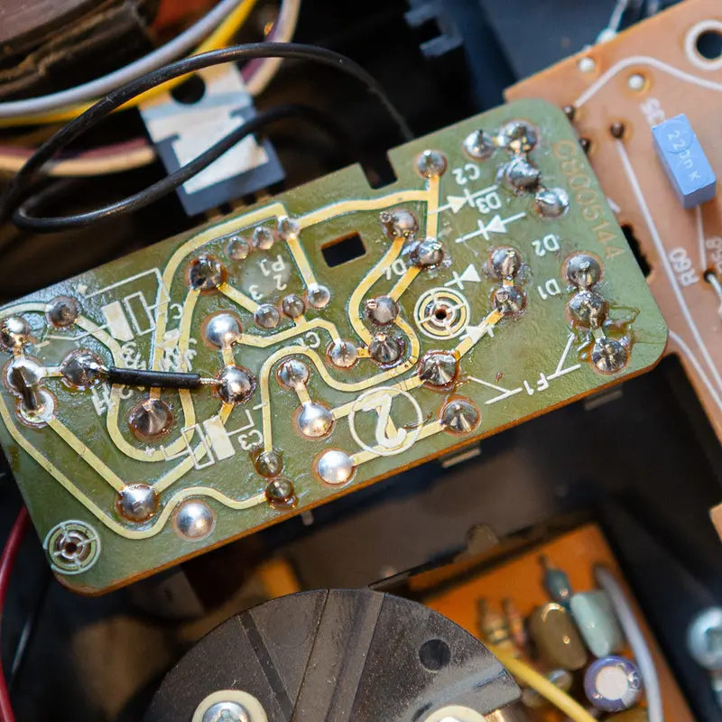
On the power supply (PCB2, 8005144)

The power supply is located in the upper left corner, just below the transformer. It is removed by using a small screwdriver to lift a plastic tap that holds it in place. 
The fuse was blown and replaced, as well as the LM7812 voltage regulator.
9

A two-legged 1000uF/40V capacitor replaced the four-legged 1000uF/40V (C3) capacitor. The original capacitor had three negative legs, so it was necessary to add a jumper at the bottom of the PCB to replicate its behaviour. The small 1uF/50V (C1) was replaced as well.
10

The rectifier diodes (D1-D4) should also be replaced. They are regular 1N4002 diodes and construct a Full-Wave Bridge Rectifier. When applied AC across the bridge, it is converted to 12V DC, e.g. for the motor and RIAA preamplifier. 
11

The diodes were all replaced by Vishay SB1H100 Schottky diodes to improve the stability of the motor.

On the motor board

The 10nF capacitor on the motor board (10M2) should also be replaced. The motor is removed by removing the single screw to the right of the motor (5).
12

The motor is removed from its casing by removing the three screws (4) at the top. 
13

After the casing is removed, the motor can be wriggled free, and the capacitor can be replaced.
14

Afterwards, the BeoGram was reassembled and ready for the next part: Adjusting the turntable.