Cleaning and lubricating the BeoLink 7000
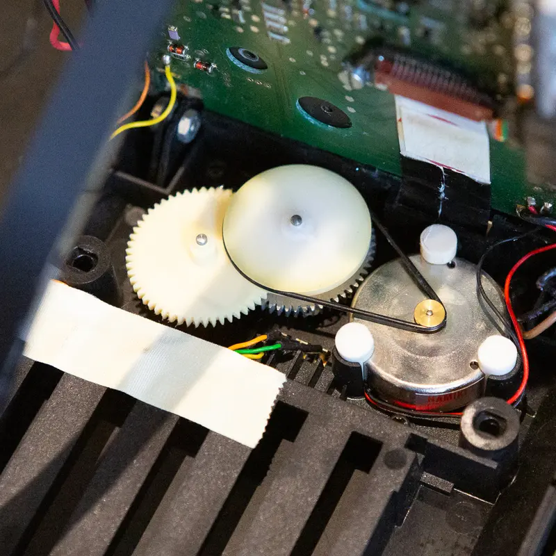
The service manual says the BeoLink 7000 hardly needs lubrication, but after 30 years the display lift benefits from it. On one remote the display stopped lifting even though the motor (9017) was running, because the belt was worn and slipping off the wheel.
The mechanism sits under PCB01, with the gear wheels (9006), the gear bar (9023) and the guide rail (9035). B&O specifies Barrierta oil for the shafts and Barrierta L 55/2 for the gears and gear bar. I take the gears and bar apart, clean and relubricate them, and put lithium grease on the guide rail.
The belt (9005) is replaced with a new NBR belt, 33 × 1 mm.
On PCB01, I replace the electrolytic capacitors with high quality 105 °C types and the TR5 fuse with a 1 A 250 V fuse. The battery wiring tends to oxidise, so I replace that too.
When the switch shafts (9007) have deteriorated, the switches don't activate and the display won't lift. I replace them with 3D printed shafts of my own design, listed under the BeoLink 7000 3D models.
More work
More on the BeoLink 7000
BeoLink 7000 overview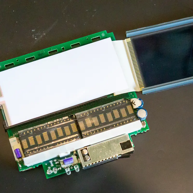
Backlight
A weak or dead backlight is the most common fault on the BeoLink 7000. The EL foil behind the display wears out, and I replace it with a new one.
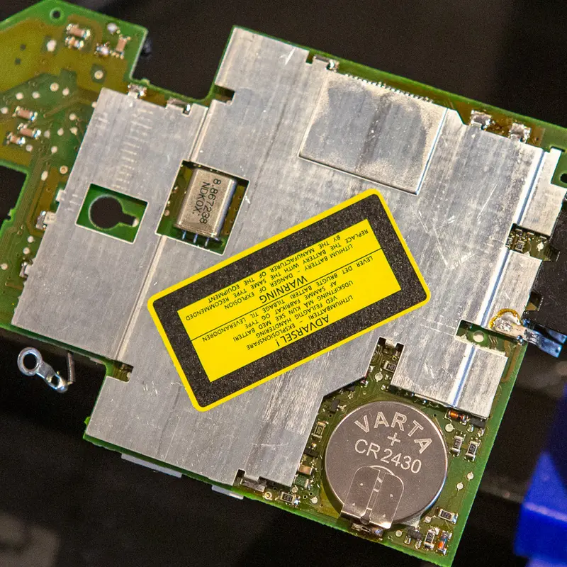
Replacing the batteries in the BeoLink 7000
The BeoLink 7000 has two batteries, the main battery and a lithium coin cell that keeps its settings. Both are long past their life, so I replace both.
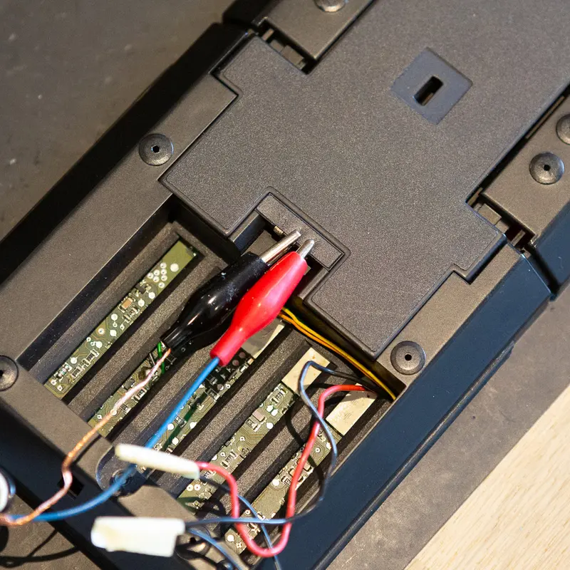
Testing the BeoLink 7000
The BeoLink 7000 has a built in test program. I use it at the end of a restoration to check the keys, the display and the memory.
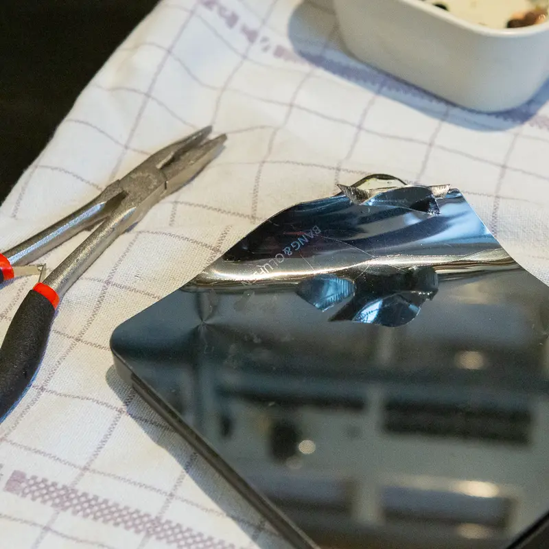
Stainless steel top plate
The top plate on the BeoLink 7000 is almost always scratched or dented. I replace it with a new plate in mirror polished stainless steel.
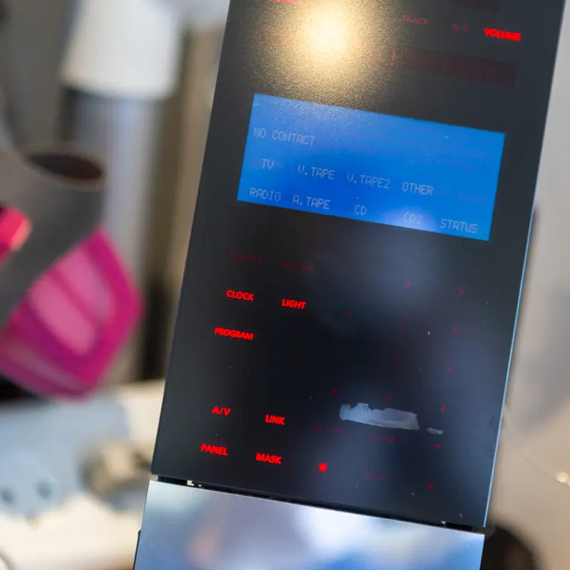
Regluing the glass front on the BeoLink 7000
Now and then the adhesive between the glass front and its plastic frame starts to let go on a BeoLink 7000. As long as it hasn't come off completely, a syringe of thin superglue fixes it.
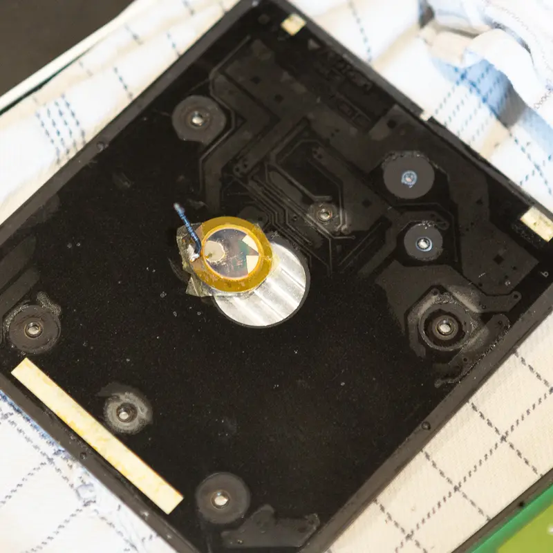
Piezo element
Tapping the top plate wakes the BeoLink 7000, thanks to a small piezo element underneath. When that stops working, the piezo has usually failed with age, and I replace it.
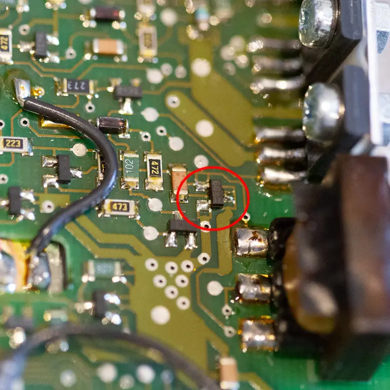
When a new backlight foil doesn't fix a BeoLink 7000
A BeoLink 7000 still had no backlight after I fitted a new EL foil. The cause turned out to be a failed transistor in the backlight oscillator.
Have a BeoLink 7000 that needs this?
Tell me about your BeoLink 7000 and what's wrong with it, and I'll get back to you.