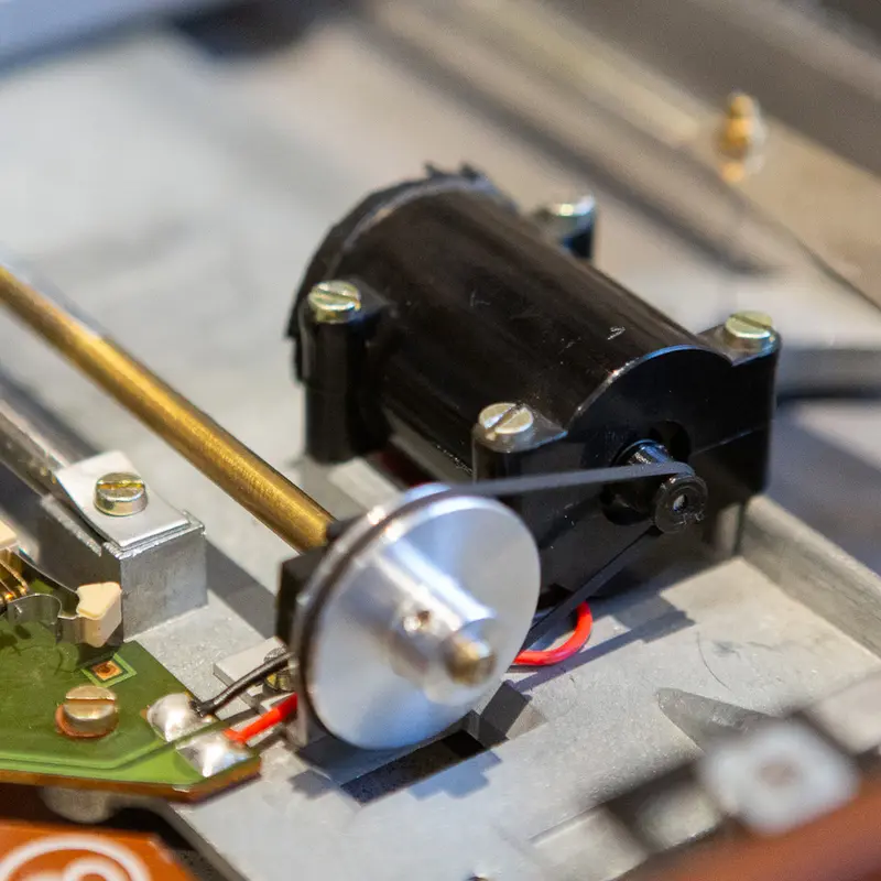
The tracking servo in the BeoGram 4002 reads the arm angle through the diaphragm arm, which sits between a small incandescent bulb and the photo resistor. The servo reacts to how much light reaches the photo resistor, so it depends on the bulb keeping a constant brightness. It doesn't. As the filament ages, its output drops and the servo's operating point drifts with it, until the bulb fails and tracking stops altogether.
Replacing the bulb isn't a real option. It's glued into its housing, and a new bulb wouldn't match the brightness the servo was originally adjusted for anyway.
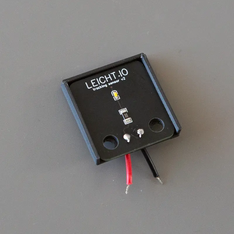
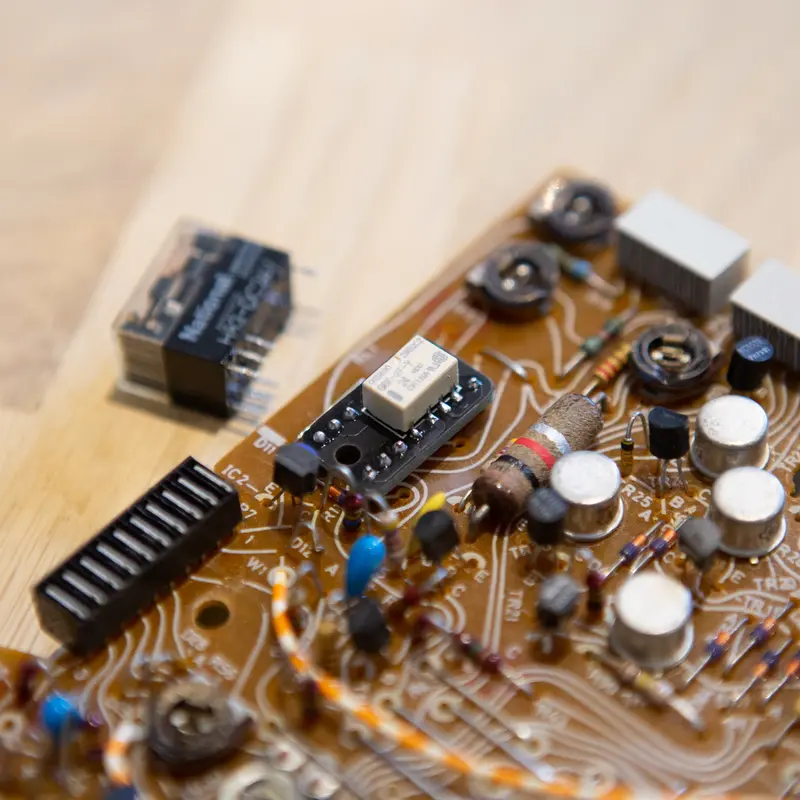
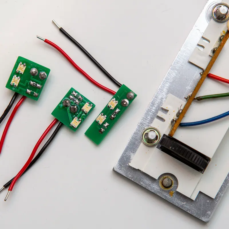
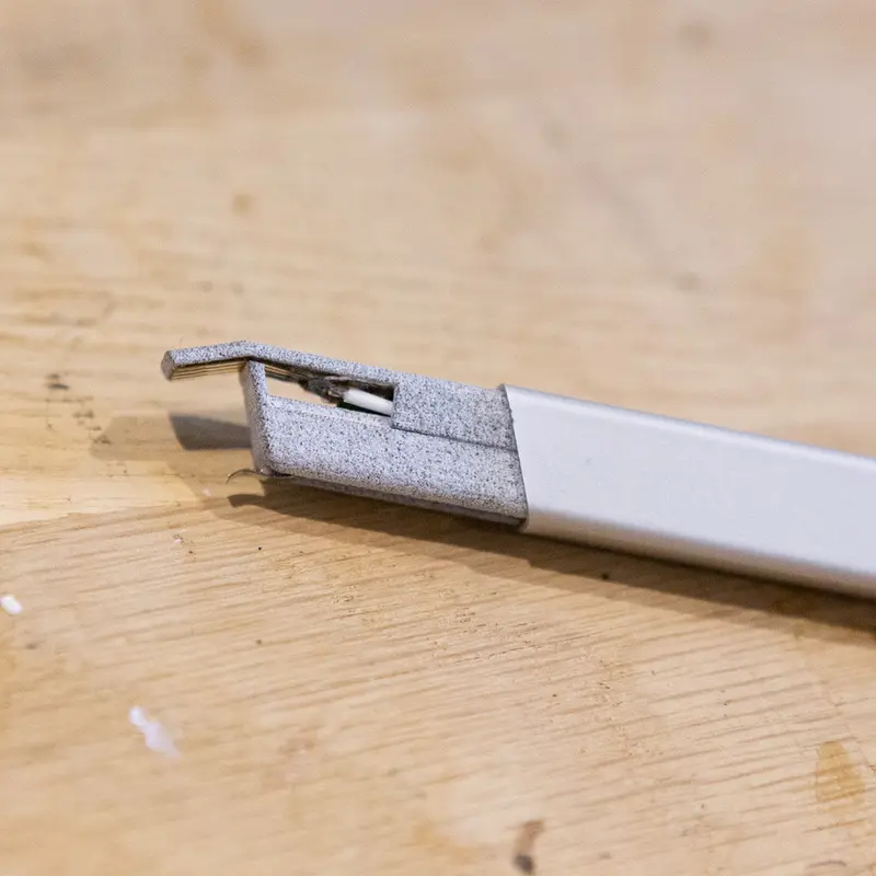
I replace it with an LED on a small PCB I designed for the job. It sits in the original position and runs from the bulb's supply, so the main board needs no changes. The LED's output stays stable over its lifetime, and it runs much cooler than the bulb did. A 3D printed cover holds the PCB in place and blocks ambient light, so only the LED reaches the photo resistor.
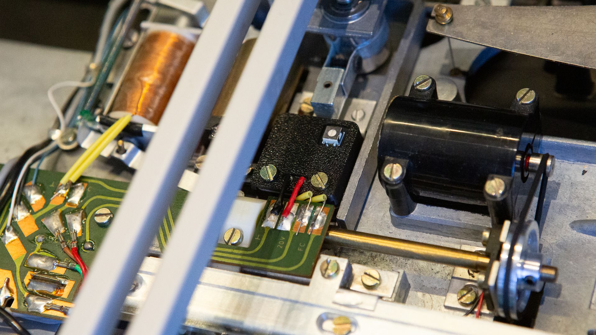
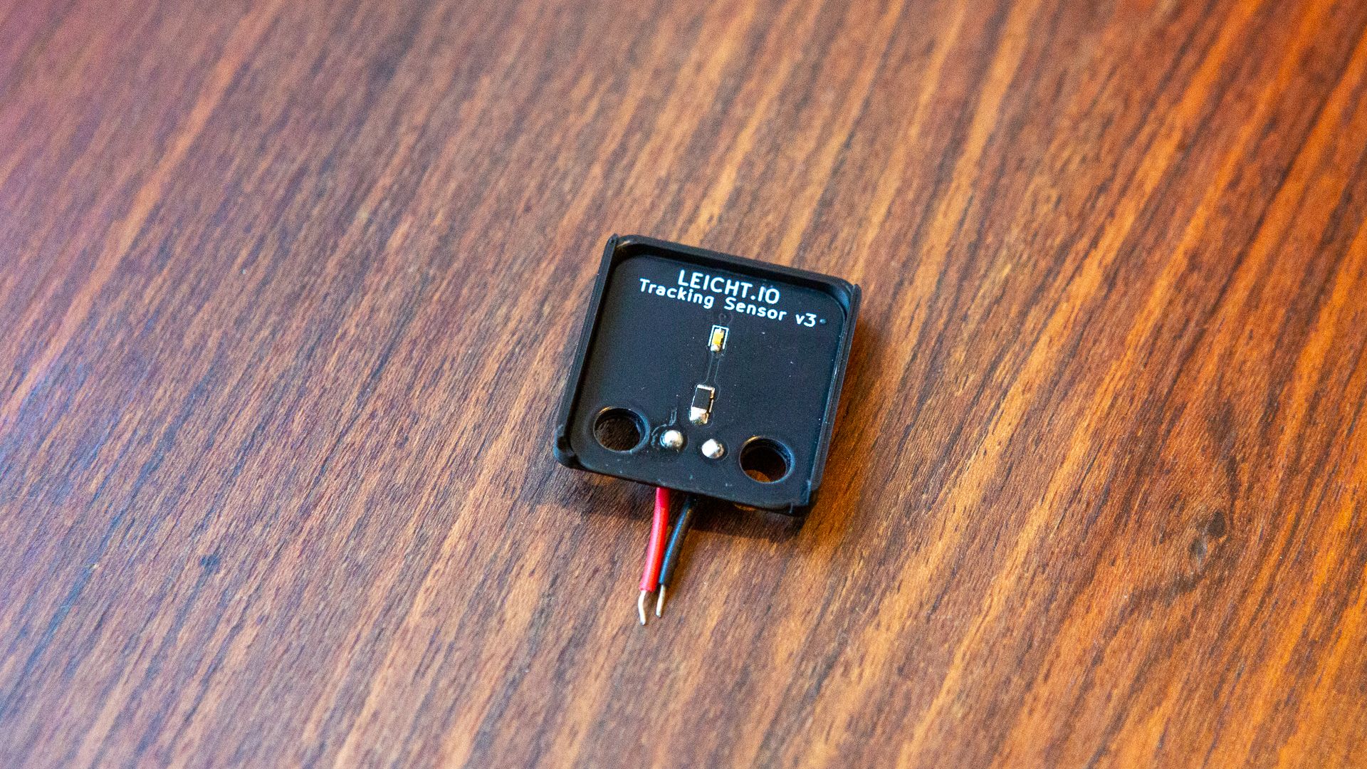
A trimmer on the back of the PCB sets the LED intensity, so the light level can be matched to what the servo expects instead of whatever a new bulb happens to give. I adjust it until the servo regulates as the service manual specifies, the first time after 2 ± 1 revolutions and then once per revolution.
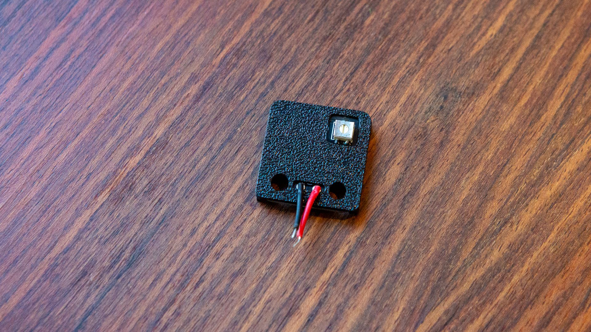
The PCB and cover are my own design, listed under parts, with the design files on GitHub.