Replacement electroluminescent (EL) backlight foil for the BeoLink 7000 display. The original foil fades with age, leaving the display dim or dark. The new foil fits behind the LCD with double-sided tape and is soldered to the display PCB.
BeoLink 7000 · Open source part
Backlight
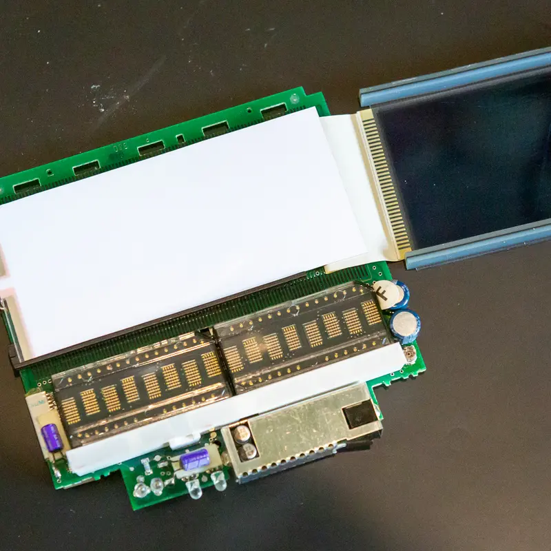
A weak or dead backlight is the most common fault on the BeoLink 7000. The EL foil behind the display wears out, and I replace it with a new one.
A weak or absent backlight is the most common fault on the BeoLink 7000.
The light comes from a white electroluminescent (EL) foil behind the blue transparent LCD, driven at about 110 V AC from the backlight transformer. EL foil has a typical lifespan of around 3,000 hours, so after 30 years most of them have faded.
To get to the foil, the remote comes apart, from the battery and the glass front to the flat flex cables between the boards and the display frame. The delicate part is the elastomeric connectors between the PCB and the display. They have to go back in exactly the same place, clean and untouched, or the display shows faulty readouts.
The old foil is held with double sided tape. The new foil goes in the same position, its leads are soldered to the display PCB, and I adjust the contrast before reassembly. The two AC wires to the display have to be routed a specific way, or the glass front won't fit properly.
The backlight is listed under parts.
More work
More on the BeoLink 7000
BeoLink 7000 overview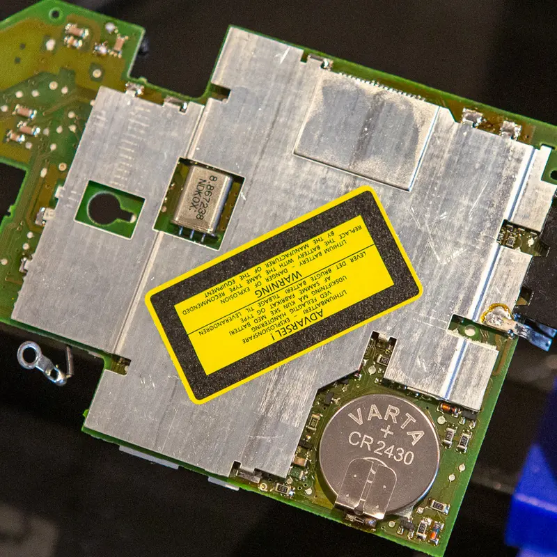
Replacing the batteries in the BeoLink 7000
The BeoLink 7000 has two batteries, the main battery and a lithium coin cell that keeps its settings. Both are long past their life, so I replace both.
Cleaning and lubricating the BeoLink 7000
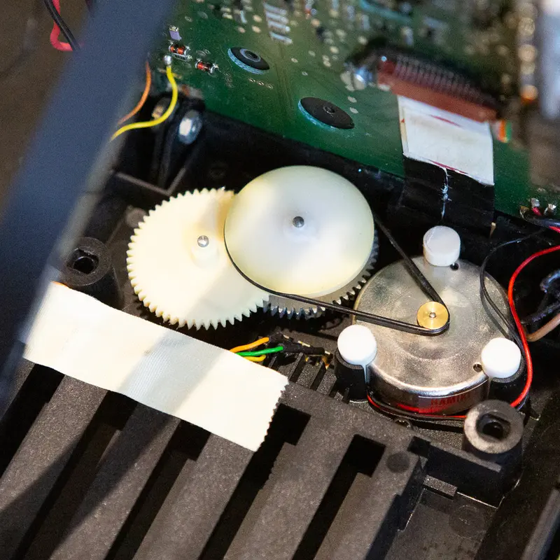
The display lift in the BeoLink 7000 runs on a small belt, gears and a guide rail. I clean and relubricate the mechanism, fit a new belt and replace the capacitors and fuse on PCB01.
Testing the BeoLink 7000
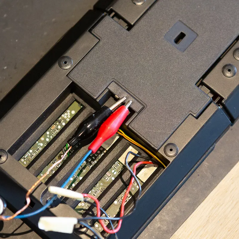
The BeoLink 7000 has a built in test program. I use it at the end of a restoration to check the keys, the display and the memory.
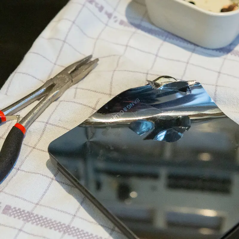
Stainless steel top plate
The top plate on the BeoLink 7000 is almost always scratched or dented. I replace it with a new plate in mirror polished stainless steel.
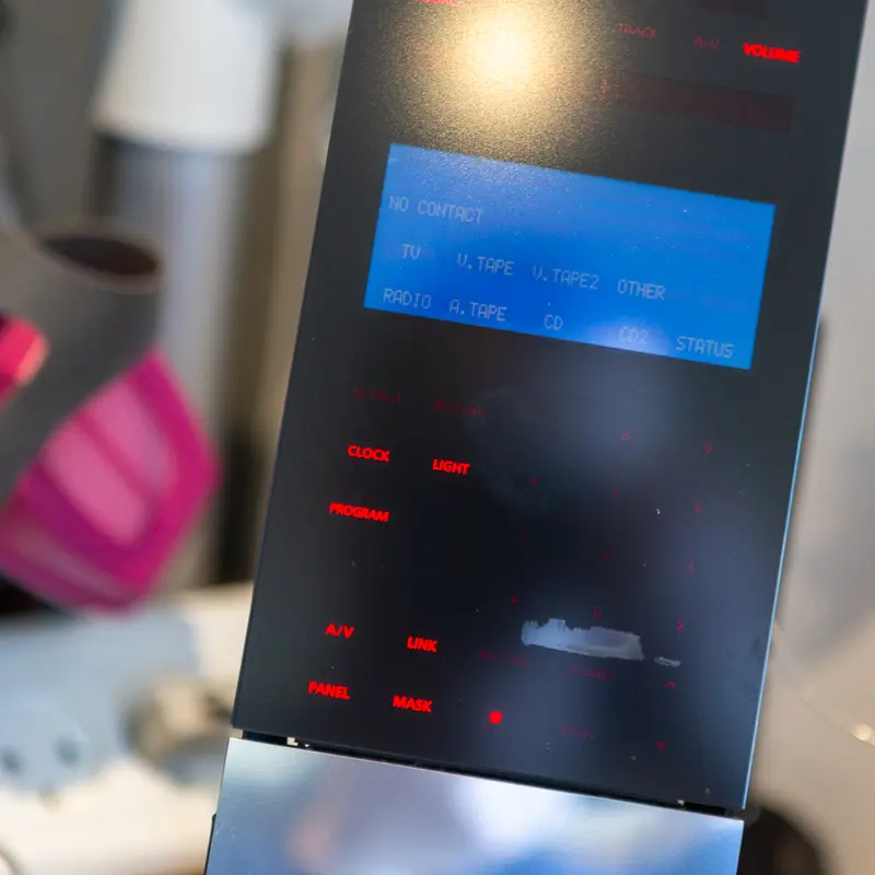
Regluing the glass front on the BeoLink 7000
Now and then the adhesive between the glass front and its plastic frame starts to let go on a BeoLink 7000. As long as it hasn't come off completely, a syringe of thin superglue fixes it.
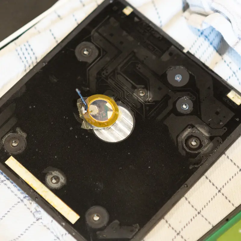
Piezo element
Tapping the top plate wakes the BeoLink 7000, thanks to a small piezo element underneath. When that stops working, the piezo has usually failed with age, and I replace it.
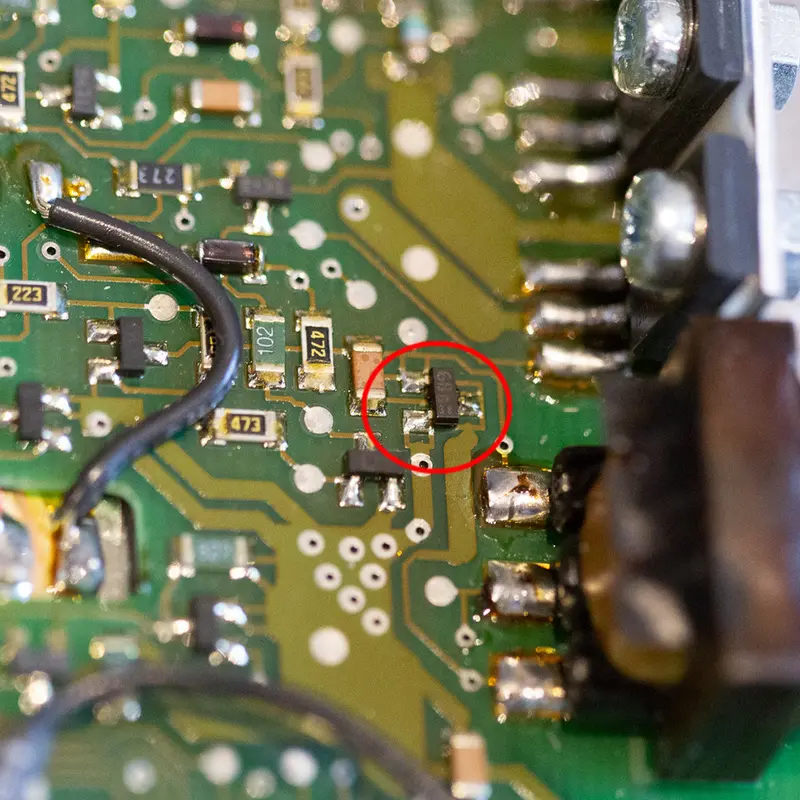
When a new backlight foil doesn't fix a BeoLink 7000
A BeoLink 7000 still had no backlight after I fitted a new EL foil. The cause turned out to be a failed transistor in the backlight oscillator.
Want one for your BeoLink 7000?
Tell me about your BeoLink 7000 and I'll get back to you.